

VMC 101: When Does a Vertical Machining Center Need a Rotary Table?
A rotary table is one of the most common options requested for a vertical machining center. It allows the workpiece to rotate, giving the cutting tool access to additional sides or features without requiring the operator to reposition the part manually. That sounds useful, and in many applications, it is. However, adding a rotary table does not automatically make every machining process faster or more accurate. The benefit depends on the workpiece, the required operations and how the part is currently being produced. Before including a rotary table in a machine quotation, we normally review the part drawing and ask what the customer expects the additional axis to do.
What Does a Rotary Table Add to a VMC?
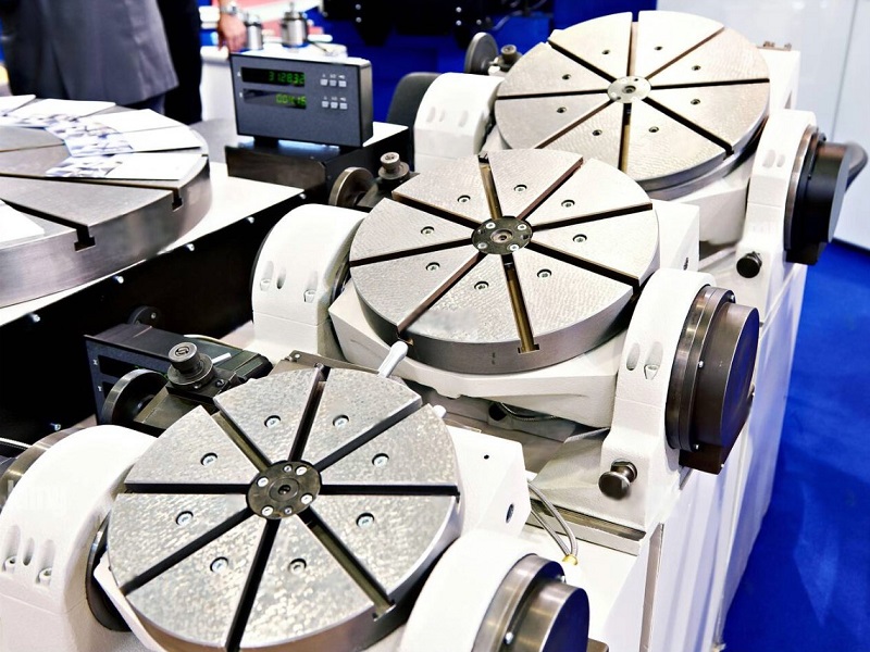
A standard three-axis vertical machining center moves along the X, Y and Z axes. The cutting tool approaches the workpiece from one main direction, so machining another side usually requires the operator to unclamp, rotate and locate the part again. A rotary table adds a rotational axis, commonly called the fourth axis or A-axis. The part can then be turned to a programmed angle while remaining in the same fixture. This is useful for components that require machining on several sides. Typical applications include:
• Holes located around the circumference of a part
• Flats, slots or keyways on different faces
• Valve bodies and small housings
• Flanges with repeated hole patterns
• Shafts requiring milling or drilling at several angles
• Parts that currently require multiple fixtures or setups
For these components, the main advantage is often not simply faster cutting. It is the ability to complete more features in one setup. Reducing the number of setups can save handling time and improve the positional relationship between features. Each time a part is removed and clamped again, there is a possibility of locating error. Keeping the part in the same fixture can make the process more consistent.
Indexing and Continuous Fourth-Axis Machining
Not every rotary-table application uses the fourth axis in the same way. In indexing work, the rotary table turns the part to a specified angle and locks in position. The machine then performs normal three-axis machining. For example, the table may rotate a square component by 90 degrees so that four sides can be drilled or milled in sequence. This type of operation is sometimes described as 3+1-axis machining. It is suitable for many multi-face components and is often the main reason customers add a rotary table to a VMC. Continuous fourth-axis machining is different. In this case, the rotary axis moves at the same time as one or more linear axes during cutting. This makes it possible to machine curved profiles, helical grooves or other features that follow the circumference of the part. Continuous machining requires the correct CNC control functions, servo system and compatible rotary table. It may also require more advanced programming. If the part only needs to be positioned at several fixed angles, full simultaneous movement may not be necessary. For this reason, the drawing should be reviewed before deciding which fourth-axis function is required.
When a Three-Axis Machine May Be Enough
A rotary table occupies space on the machine table and adds cost to the complete system. It should be selected because the part needs it, not simply because a fourth axis may be useful someday. If the component only requires machining from one direction, a standard three-axis VMC is normally sufficient. Some multi-face parts can also be produced efficiently with a well-designed fixture, especially when the production volume is low, and the additional setups do not affect critical dimensions. The expected production quantity matters here. For a small number of simple parts, manual repositioning may be acceptable. When the same part is produced repeatedly, reducing setup and handling time becomes more valuable. We also consider whether the rotary table will remain installed for most jobs or only be used occasionally. A customer producing a wide variety of parts may prefer a removable setup, while a dedicated production machine can be arranged around a specific rotary-table application.
Points to Check Before Selecting a Rotary Table
The table diameter is an obvious specification, but it is not the only factor that determines whether a rotary table is suitable. The complete setup must fit inside the machining area. This includes the rotary table, chuck or fixture, workpiece and, where required, a tailstock. A rotary table can reduce the usable X-, Y- or Z-axis travel, depending on how it is installed. The following items should be checked before the configuration is confirmed:
• Workpiece dimensions and weight
• Rotary-table diameter and load capacity
• Chuck, fixture and tailstock arrangement
• Swing diameter and possible interference
• Available machine travel after installation
• Required indexing accuracy
• Clamping torque and cutting load
• Vertical or horizontal mounting position
• CNC controller and fourth-axis interface
• Whether indexing or continuous movement is required
Tool access is also important. A part may physically fit on the rotary table but still be difficult to machine if the spindle, tool holder or machine enclosure interferes at the required angle. For longer workpieces, a tailstock may be needed to provide additional support. The tailstock position and centre height must match the rotary table, and both components must fit within the available machine travel. These details are easier to confirm from a drawing than from the workpiece diameter alone.
The Rotary Table Is Part of the Process
When evaluating a fourth-axis machining application, we look beyond the rotary table itself. The fixture must hold the workpiece securely while allowing access to the required features. Cutting forces should remain within the capacity of the table and its clamping system. The selected zero position, machining sequence and cable arrangement must also be considered.For production applications, chip accumulation around the fixture can become an issue. Coolant flow and chip removal should therefore be reviewed, particularly when the table is mounted vertically or when the workpiece contains pockets that can collect chips. Programming and operator experience are also part of the decision. A rotary table can simplify part handling, but more complex simultaneous machining may require suitable CAM software and additional programming knowledge. For many customers, the most practical solution is not the most advanced configuration. It is the one that completes the required features with a stable setup and a manageable process.